| Amplifier |
Symbols - Amplifier
|
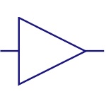
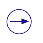
Basic Amplifier
An amplifier is a device that amplifies a relatively
small input signal i.e. it increases the power of the
signal. They are used in communication systems, audio
devices etc |
|
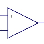
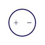
Operational
Amplifier
Operational Amplifier (Op Amp) is a voltage amplifier
with very high gain. The input is differential. They are
used in instrumentation devices, signal processing,
control systems etc |
|
| Antenna |
Symbols - Antenna
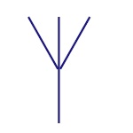 |
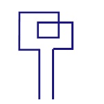
Antenna
This symbol belongs to Aerial or Antenna. It converts
electrical power into radio waves. It is used in
wireless communication to transmit or receive the
signals. |
|
Loop Antenna
Loop antenna is named after its loop like shape of wire
or other electrical conductor. They are used as
receiving antennas in low frequency range. |

|
Dipole Antenna
It is most widely used antenna.Generally used in set-top
TV, shortwave transmission and FM receivers. |
|
| Audio |
Symbols - Audio
|
Buzzer
This is sound producing device. This produces buzz sound
when the voltage is applied. |
|
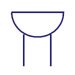
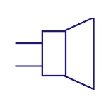
Loud Speaker
Th |
|
| Capacitor |
Symbols - Capacitor
|
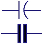
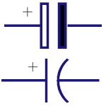
Non Polarized
Capacitor
Capacitor stores the charge in the form of electrical
energy. These two symbols are used for non-polarized
capacitor. Non-polarized capacitors are big in size with
small capacitance. They can be used in both AC and DC
circuits. |
|
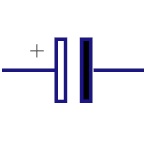
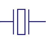
Polarized Capacitor
Polarized capacitors are small in size but have high
capacitance. They are used in DC circuits. They can be
used as filters, for bypassing or passing low frequency
signals |
|
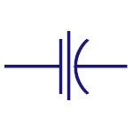
Electrolytic
Capacitor
Almost all electrolytic capacitors are polarized and
hence used in DC circuits |
|
Feed through
Capacitor
They provide low impedance path to ground for high
frequency signals |
|
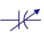
Variable Capacitor
The capacitance of the variable capacitor can be
adjusted by turning the knob. They are widely used to
adjust the frequency , that is for tuning. |
|
| Convert |
Symbols - Convert
|
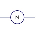
Motor
This converts the electric energy to mechanical energy.
|
|
ADC
Analog to Digital converter is used convert analog
signals (usually voltage) to digital values. |
|
DAC
Digital to Analog converter is used to convert digital
code to analog signals. |
|
| Crystal Oscillator |
Symbols - Crystal Oscillator
|
Crystal Oscillator
Used to generate clock signal of very precise frequency.
|
|
| Diode |
Symbols - Diode
|
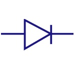
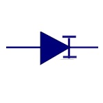
Pn Junction Diode
A PN junction diode allows the current to flow only in
forward bias condition. These diodes can be used in
clipping and clamping circuits , as rectifiers in dc
circuits etc. |
|
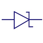
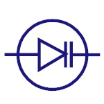
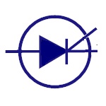
Zener Diode
In forward bias condition, it acts as normal diode and
allows current. It also allows current to flow in
reverse bias condition when the voltage reaches a
certain break-down point. Generally used in voltage
regulator and over voltage protection circuits. |
|
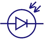
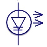
Photodiode
Photodiode detects the light energy and converts it into
current or voltage by a mechanism called photoelectric
effect. These are used in CD players , Cameras etc. |
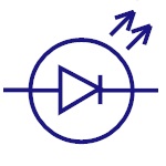 |
Led
Light emitting diode is similar to PN junction diode but
they emit energy in the form of light instead of heat.
These are mostly used in indication , lightening
applications. |
|
Varactor Diode
Varactor diode is called varicap or variable capacitance
diode. The capacitance of this diode varies according to
the applied input voltage. This is used in frequency
controlled oscillators , frequency multipliers etc. |
|
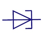
Shockley Diode
This is a four layer diode. This had fast switching
operation and hence is used in switching applications.
|
|
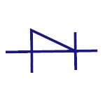
Schottky Diode
It represents Schottky diode. It has low forward voltage
drop and it can switch rapidly. Used in voltage
clamping, rectifiers, reverse current and discharge
protection |
|
Tunnel Diode
This is also known as Esaki diode.It can switch very
fastly and can perform well in micro wave frequency
range. This is used in oscillator circuits and micro
wave circuits. |
|
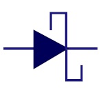
Thyristor
It consists of four layers of alternating P and N
materials. They act as bistable switches and are used in
circuits where high voltages and currents are involved.
|
|
Constant Current
Diode
Also called as Current Limiting Diode or Current
Regulating Diode. It limits the current to a specified
maximum value. |
|
Laser Diode
The laser diode is similar to light emitting diode. The
active region is formed in intrinsic region in PIN
structure. Laser diodes find its applications in laser
printing, laser scanning etc. |
|
| Fuse |
Symbols - Fuse
 |
Fuse
Symbol represents the fuse that protects the circuit
from over current. |
|
| Ground |
Symbols - Ground
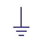 |
Ground
It is equivalent to theoretical 0V and is used as zero
potential reference. It is the potential of perfectly
conducting earth. |
|
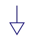
Signal Ground
It is a reference point from which the signal is
measured. There may be several signal grounds in a
circuit due to the voltage drops in a circuit. |
|
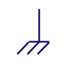
Chassis Ground
It acts as a barrier between user and the circuit and
prevents electric shock. |
|
| Inductor |
Symbols - Inductor
|
Iron Core Inductor
These are used as substitutes to ferrite core inductors.
Ferrite core or Ferromagnetic inductors have high
permeability and require air gap to reduce it. Iron
powdered core inductors have this air gap integrated.
|
|
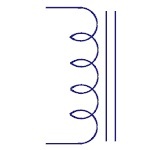
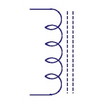
Ferrite Core
Inductors
Core material, in this type of inductors is made of
ferrite material. These are mostly used to suppress the
interference of electromagnetic waves. |
|
Center Tapped
Inductors
These are used in coupling of signals |
|
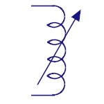
Variable Inductors
Movable ferrite magnetic core variable inductors are
most common. The inductance is varied by sliding the
core in or out of the coil. |
|
| Light Bulb |
Symbols - Light Bulb
 |
Light Bulb
The symbol represents the light bulb. The bulb glows
when required voltage is applied. |
|
| Logic gate |
Symbols - Logic gates
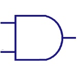 |
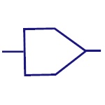
And Gate
This is the basic gate and it implements logical
conjunction. The output of the AND gate is high, only if
both the inputs are high otherwise both are low. |
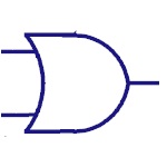 |
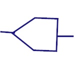
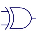
Or Gate
The OR gate implements logical disjunction.The output is
high if any one of the inputs is high. |
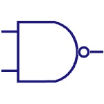 |
Nand Gate
It is complement of AND gate. The output is low only
when both the inputs are high, otherwise it is high.
|
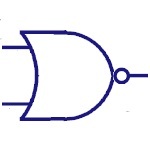 |
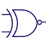
Nor Gate
NOR gate is a not OR gate. Output of this gate is high,
if both the inputs are Low, otherwise it is High. |
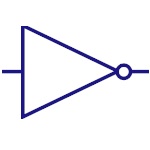 |
Not Gate
Inverter or NOT gate implements logical negation. This
gate inverts the input. |
|
Exor
This gate implements exclusive OR logic. The output of
this gate is high ,if both the inputs are different.
|
|
Exnor
This gate implements negation of EXOR logic. The output
of this gate is high , only if the two inputs are
identical. |
|
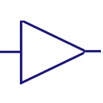
Buffer
It is an audio signaling device. Generally used in
alarms, timers and for confirmation messages. |
|
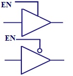
Tri-State Buffer
Similar to a normal buffer but with a control signal. In
case of active high buffer, it operates normally only
when control signal is 1. In case of active low buffer,
it operates normally only when control signal is 0. |
|
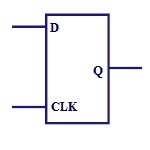
Flip Flop
Flip flop is the also a memory element but this is a
synchronous device. The figure below shows the basic D- |
|
| Resistor |
Symbols - Resistor
|
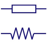
Fixed Resistor
It is a device that opposes the flow of current in a
circuit. These two symbols are used to represent fixed
resistor. |
|
| Resistor Variable |
Symbols - Resistor Variable
|
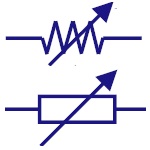
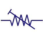
Rheostat
It is a two terminal variable resistor. They are
generally used to control the current in the circuit.
Generally used in tuning circuits and power control
applications like heaters, ovens etc |
|
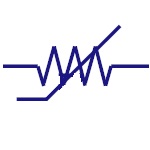
Preset
It is a mini variable resistor. It is also called
Trimmer Resistor or Trim Pot. The resistance is adjusted
with rotary control present on top of it with the help
of a screw driver. They are used to adjust the
sensitivity of the circuit like temperature or light.
|
|
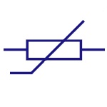
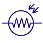
Thermistor
It is a temperature sensitive resistor. They are used in
temperature sensing, current limiting circuits,
over-current protection circuits etc. |
|
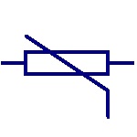
Varistor
It is a Voltage Dependent Resistor. It has non-linear
current-voltage characteristics. Generally used in
circuit protection from voltage surges and excessive
transient voltages. |
|
Magneto Resistor
They are also called as Magnetic Dependent Resistors
(MDR). The resistance of magneto resistor varies
according to the external magnetic field strength. They
are used in electronic compass, ferrous material
detection, position sensors etc. |
|
LDR
They are also called as Photo Resistors. The resistance
of LDR varies with the intensity of the light incident
on it. They are generally used in light sensing
applications. |
|
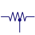
Tapped resistor
A wire-wound type fixed resistor with one or more
terminals along its length. Generally used in voltage
divider applications. |

|
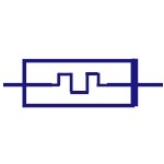
Attenuator
It is a device used to lower the power of a signal. They
are made from simple voltage dividers and hence can be
classified in the family of the resistors. |
|
Memristor
The resistance of memristor is varied according to the
direction of flow of charge. Memristors can be used in
signal processing, logic/computation, non-volatile
memory etc. |
|
| Sources |
Symbols - Sources
|
AC Supply
This represents AC supply in the circuit. |
|
DC Supply
This represents the DC power supply. It applies DC
supply to the circuit. |
|
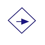
Constant Current
Source
The symbol represents an independent current source
which delivers constant current. |
|
Controlled current
Source
It is a dependent current source. Usually depends on
other sources (voltage or current). |
|
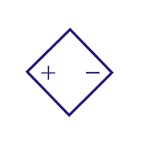
Controlled Voltage
Source
It is a dependent voltage source. Usually depends on
other sources (voltage or current). |
|
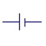
Single Cell Battery
This provides supply to the circuit. |
|
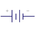
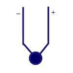
Multi Cell Battery
Combination of multiple single cell batteries or a
single large cell battery. The voltage is usually
higher. |
|
| Switches |
Symbols - Switches
|
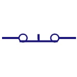
Push Button
(Normally Open)
This switch is in ON state when the button is pressed
otherwise it is in OFF state. |
|
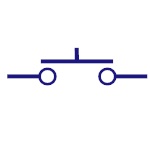
Push Button
(Normally Closed)
This switch is initially in ON state. This goes to OFF
state when it is released. |
|
Spst Switch
Single pole single throw is abbreviated as SPST. This
acts as ON/OFF switch. Poles define the number of
circuits it can be connected to and throws defines the
number of positions that a pole connects. |
|
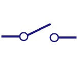
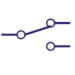
Spdt Switch
Single pole double throw is abbreviated as SPDT. This
switch allows the current to flow in any one of the two
directions by adjusting its position. |
|
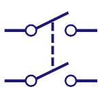
Dpst Switch
Double pole single throw is abbreviated as DPST. This
switch can drive two circuits at a time. |
|
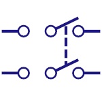
Dpdt Switch
Double pole double throw is the full form of DPDT. This
can connect the four circuits by changing the position.
|
|
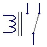
Relay Switch
This represents the relay switch. This can control the
AC Loads using the DC voltage applied to the coil. |
|
| Termocouple |
Symbols - Thermocouple
|
Thermocouple
It is used to measure temperature. |
|
| Transformer |
Symbols - Transformer
|
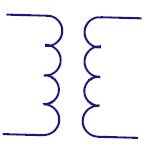
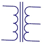
Transformer
Transformer is the basic element that transfers energy
in one circuit to the other circuit through
electromagnetic induction. They are generally used in
electric power applications to increase or decrease the
voltage of AC current. |
|
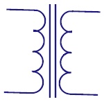
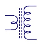
Iron Core
Uses a piece of magnetic material as core. Generally
Ferro magnetic metals like iron are used. The core has
high permeability and is used to confine the magnetic
field. |
|
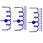
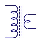
Center Tapped
The center tapped transformer has its secondary winding
divided into two parts with same number of turns in each
part. This results in two individual output voltages
across two line ends. Used in rectifier circuits. |
|
Step Up Transformer
The no. of turns in secondary winding is more than that
of primary winding. The output voltage is higher than
input voltage. Significantly used in inverters. |
|
Step Down
Transformer
The no. of turns in secondary winding is less than that
of primary winding. The output voltage is lesser than
input voltage. It is widely used in low power
applications. |
|
| Transistor |
Symbols - Transistor
|
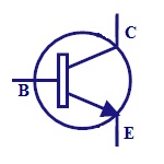
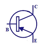
NPN
It is made of combination of P-type semiconductor
between two N-type semiconductors. It is switched ON
when the base-emitter junction is forward biased. They
are commonly used for amplifying and switching
applications. |
|
PNP
It is made of combination of N-type semiconductor
between two P-type semiconductors. It is switched ON
when the base-emitter junction is reverse biased. These
are used for amplifying and switching applications. |
|
| Transistor Darlington |
Symbols - Transistor Darlington
|
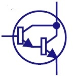
Darlington
Transistor
This configuration produces high current gain. They are
used in power regulators, output stages of audio
amplifiers, display drivers etc. |
|
| Transistor JFET |
Symbols - Transistor JFET
|
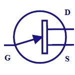
N- Channel JFET
N-channel JFET is made by n-type silicon bars which form
two PN junctions at the side. Majority charge carriers
here are electrons. |
|
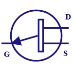
P-Channel JFET
P-Channel JFET is made by p-type silicon bar which forms
two PN junctions at the side. Majority charge carriers
here are holes. |
|
| Transistor MOSFET |
Symbols - Transistor MOSFET
|
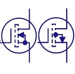
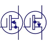
Enhancement MOSFET
The enhancement mode MOSFET has positive gate operation.
It induces negative charges into the n-channel and thus
number of negative charges increases, enhancing the
channel conductivity. |
|
Depletion MOSFET
The depletion mode has negative gate operation. This
decreases the width of the depletion layer. |
|
| Transistor Photo |
Symbols - Transistor Photo
|
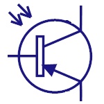
Phototransistor
The photo transistor converts the light energy falling
on it to its corresponding electrical energy. This can
be used in light sensing applications.Base is left
disconnected as light is used to enable the flow of
current. |
|
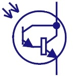
Photo Darlington
Photo Darlington Transistor is similar to
phototransistor with very high gain and sensitivity |
|
| Wave generators |
Symbols - Wave Generators
|
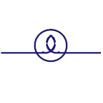
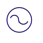
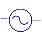
Sinusoidal Generator
Represents sine wave generator. |
|
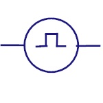
Pulse Generator
Represents pulse or square wave generator. |
|
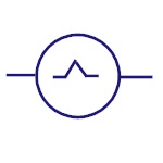
Triangular Wave
Represents triangular wave generator. |
|
| Wires |
Symbols - Wires
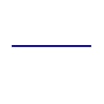 |
Wires
Represents a conductor that conducts electrical current.
Also called a power line or electric line or wire. |
|
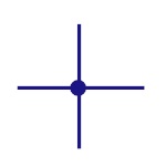
Connected Wires
Represents the connection of two conductors. Dot shows
the junction point. |
|
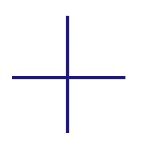
Unconnected Wires
Represents two unconnected wires/conductors. |
|
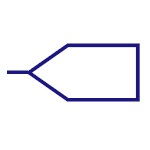
Input Bus Line
Represents a bus for input or incoming data. |
|
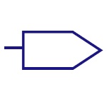
Output Bus Line
Represents a bus for output or outgoing data. |
|
Terminal
Represents start or end point. |
 |
Bus Line
Represents a number of conductors joined together to
form a bus wire. |
|